Introduction
That title is already a mouthful! Let’s start by breaking it down into intelligible pieces:
- LILYGO: the Chinese company that designed and produced this board. They sell many other dev boards and peripherals primarily around IoT (Internet of Things).
- T5: the model of the board.
- 4.7": the size (diagonal) of the screen (≈11.9cm).
- e-paper: the type of screen. E-paper is a type of display technology that is energy efficient and is most commonly used for e-readers (Kindle…). It does not require to be powered to keep showing pixels.
- ESP32-S3: the microcontroller (compute unit) on the board. The ESP32-S3 is a powerful microcontroller that is widely used in many IoT devices (in part thanks to its built-in WiFi and Bluetooth support).
- Development board: a board that is designed to be used by developers to test and develop software for a particular product.
In short, with this board, we have everything we need to start having some fun with an e-paper screen of a good size and a powerful microcontroller!
You can get the board from LILYGO official website or from AliExpress, where I got mine. The AliExpress listing mentions V2.3, but I actually received the V2.4!
Hardware overview
The screen
You likely got this dev board to play with e-paper, so let’s first have a peek at the screen’s key specs (complete datasheet):
- Model: ED047TC1
- Size:
- Diagonal: 4.7" (11.9cm)
- Width: 4" (10.7cm)
- Height: 2.3" (5.8cm)
- Resolution: 540x960 pixels
- Color: 16 gray levels
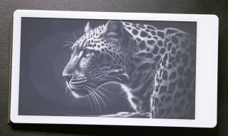
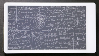
The size of the screen is great relative to the price range. The resolution and grayscale allow displaying both sharp images and text. That makes this screen really versatile, and it should support a wide range of projects! Here are a few pictures I took to demonstrate the quality of the display rendering:
Visual overview of the board
I took a high-resolution picture (click for full resolution) of my board and annotated it:
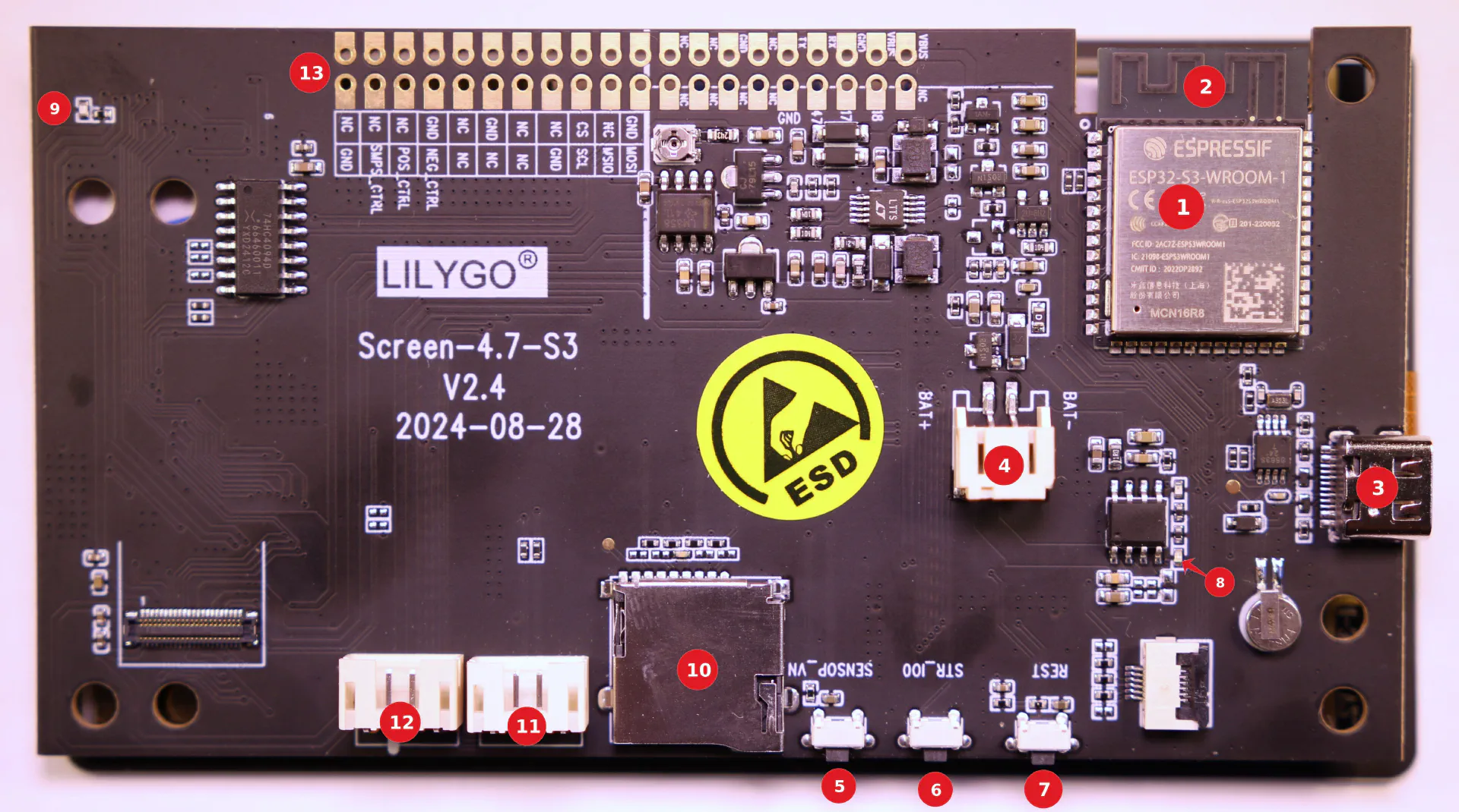
Annotated LILYGO T5 4.7" e-paper ESP32-S3 board
Microcontroller ESP32-S3-WROOM-1 N16R8. N16 indicates 16MB of flash memory is available (non-volatile memory where your program is stored), while the R8 refers to the 8MB of PSRAM memory available (volatile memory your program can use to allocate variables). It is a “high-memory” configuration to allow loading and handling images for the e-paper screen.RF (Radio Frequency) antennaof the ESP32 used for WiFi and Bluetooth connectivity.USB-C port, used to program the board(aka “flash the firmware”). It can also just power the board.JST 2.0mm 2-pin connector to power the board with a battery. I haven’t used the board on battery yet; I will report back if I do.User button(pin IO21): a button that is free for you to use in your application.BOOT buttonis used to enter bootloader mode (the mode required to upload your program to the board). See note at the end of this article on how/when to use it.RESET buttonwill reset (restart) the board.Green LEDshowing that the board is powered.Blue LEDthat lights up when the e-paper screen is powered. Useful to notice that you forgot to power off the screen when it’s not in use.Micro SD card reader.JST 4-pin connector, pins: [G|IO45|IO48|V](from left to right, as seen in the picture). You should have received one female connector cable with your purchase to plug in. Note that the V pin can produce a 3.3V voltage, but only if the e-paper screen is powered (i.e., you calledepd_poweronand the blue LED is lit up).JST 4-pin connector, pins: [G|IO16|IO15|V](ditto line above for the rest).40-pin compatible with Raspberry PI. Note that the vast majority of those are noted NC, for Not Connected. Actually, there are only 4 free-to-use pins there. See the section below Pins free to use for details.
The complete schematic of the board is available on GitHub.
A quick note on consumption: ESP32 microcontrollers are not particularly famous for their low power consumption, but according to this GitHub issue, the consumption can go as low as 0.38mA in deep sleep, which with a 2000mAh battery would last 219 days (arguably, 219 days of deep sleep is not very useful, and any rock in your garden would produce the same outcome, without any battery).
Other side of the board
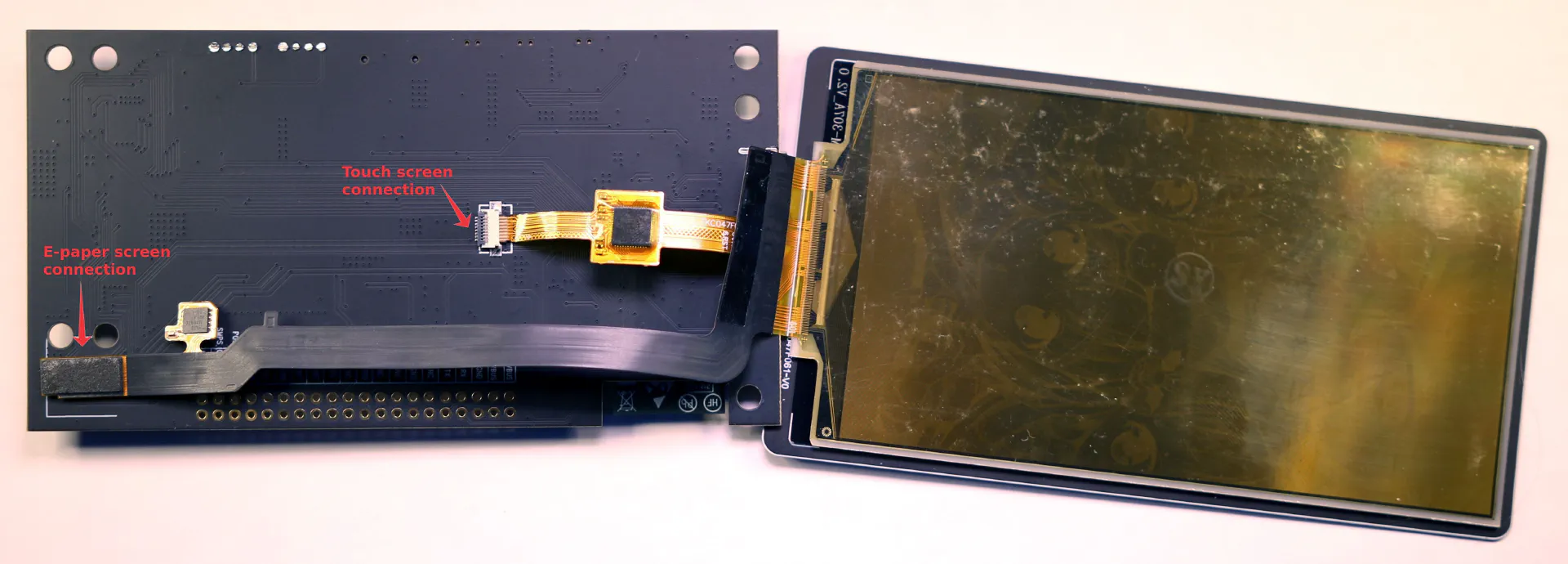
Other side of the LILYGO T5 4.7" e-paper ESP32-S3 board
Note that the touch screen can easily be disconnected/reconnected thanks to the ZIF (Zero Insertion Force) connector.
Pins free to use
Most pins of the ESP32 are used for the proper functioning of the board (notably, to control the screen). If you want to connect additional components to this board, your choice is going to be limited. Here’s what I found:
4 pins are completely free to use and easily connected to:
IO45: on the JST 4-pin annotated (11), it’s the 2nd pin from the left. It is also connected to the pin markedSCL.IO48: on the JST 4-pin annotated (11), it’s the 3rd pin from the left. It is also connected to the pin markedMSIO(misspelling of MISO). (Note that on this official pic, it seems that MISO/SCL labels have been incorrectly swapped).IO10: onMOSIpin.IO39: onCSpin.
Note that these pins correspond to the pins of an SPI bus (SCLK/MOSI/MISO/CS), making it usable to interface with an external device or sensor.
Additionally, if you don’t use the SD card reader, you can use its 4 pins:
IO15: on the JST 4-pin annotated (12), it’s the 3rd pin from the left.IO16: on the JST 4-pin annotated (12), it’s the 2nd pin from the left.IO11: not connected to anything easily accessible. You’d need to solder directly on the ESP32 pin.IO42: not connected to anything easily accessible. You’d need to solder directly on the ESP32 pin.
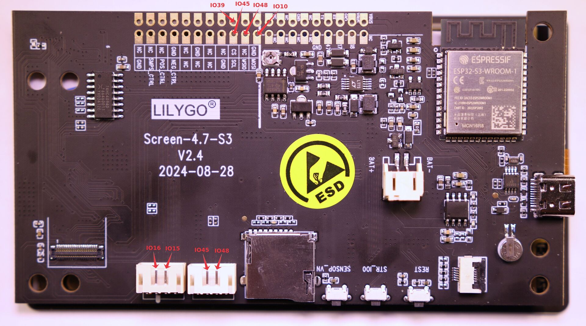
Free pins on the LILYGO T5 4.7" e-paper ESP32-S3 board
Programming
To program that board, I use VSCode with PlatformIO. When setting up your project, search for lilygo-t-display-s3 in the boards registry.
Your main resource for programming is the official GitHub repo Xinyuan-LilyGO/LilyGo-EPD47 (branch esp32s3). Make sure to read the README.MD once.
Here’s an overview of the main folders of the repo:
boards: contains JSON definitions of the board to use in theplatform.io. As noted above, I don’t think you need this anymore as the board is already listed in the global registry of PlatformIO.datasheet: contains the datasheet of the ED047TC1 screen.docs: mostly empty. I would not be writing this post if the documentation was great :).examples: a collection of examples using the board. See below for an overview of each.firmware: contains the factory firmwares. You should not need to use those unless you wanted to do a hard factory reset of your board.schematic: contains the schematic of the board. If you are interested in electronics and want to know what components are being used and how they are wired.scripts: contains some useful Python scripts to convert font files (fontconvert) or images (imgconvert) into header (.h) files you can use to draw on the screen.shell: contains STL files to 3D print a case (shell) for your board, with different styles.src: library files to simplify the usage of the board.
The main way I learned to program this board was by flashing every example one by one, seeing what they do, and reading the code to see how it was done. Here’s a short description of each example so you can jump on whichever is closest to your needs:
button: basic example using the built-in user button (annotated (5) on the picture).demo: this should be the demo program running when you receive the board. It shows off most features of the board in a single screen: draw image/text/geometric shape, partial refresh, touch screen, deep sleep, SD card reader init…drawExample: demo of manual drawing: lines, circles, rectangles.drawImages: demo drawing of images. Display 3 images stored in header files in a loop.grayscale_test: display various gradients of grey.screen_repair: partial refresh of the screen can leave some persistent residual traces (aka ghosting), and if done too often or for too long might even do irreversible damage. That program can help remove some of the residual images by refreshing the entire screen with alternation of black and white screens.sleep: demo deep sleep mode with time-based wake-up.spi_driver: set the board as an SPI slave that receives commands to control the e-paper screen (display images). Note that this makes use of the free SPI pins mentioned earlier.touch: basic example of detecting when the capacitive screen is touched.wifi_sync: a more complex example that starts a web server athttp://lilygo.localon your local WiFi network for handling requests to store image files (on flash or SD card) and display the images.
Here’s a dump of various things I learned when programming this board:
- You should use PSRAM to store images in memory; that’s the main reason this board has 8MB of it. Allocate your memory buffer with
ps_mallocorps_callocinstead of the traditionalmalloc/calloc. In the examples, you might also see the usage ofheap_caps_malloc(..., MALLOC_CAP_SPIRAM), which is just an alternative way to do the same. - You’ll notice that the examples allocate a
uint8_tarray of sizeEPD_WIDTH * EPD_HEIGHT / 2to buffer the image to draw full screen using theepd_draw_grayscale_imagefunction. But why the/ 2?! The screen supports a 16 gray level color scheme, 16=2^4, so in a single byte you can store the color value of 2 pixels. This is howepd_draw_grayscale_imagewill read the buffer. Eachuint8_tencodes for 2 consecutive pixels on the x-axis, and each value is simply obtained with a mask& 0x0For& 0xF0(you can see that in theepd_draw_pixelfunction of theepd_driver.cfile). - One of the main advantages of e-paper screens is that they don’t need to be powered to keep displaying pixels. When programming, you should power on (
epd_poweron()) the screen only when you need to update it, and then immediately turn it back off. There are two functions to power off:epd_poweroffandepd_poweroff_all. The main difference seems to be thatepd_poweroffkeeps the blue LED at the back of the board powered (which is wasteful and also removes a useful indicator of when the screen is powered or not), so I see little reason not to always useepd_poweroff_all. - Not specific to this board, but the ESP32-S3 cannot connect to 5GHz WiFi networks, only the classic 2.4GHz.
- If you intend to use the SD Card reader, I found the functions in this article useful, in particular the
listDirfor debugging. - If the ESP32 is in (deep) sleep, you won’t be able to flash it directly from your IDE. You will get an error like this:
|
|
In this case, you need to manually switch to “bootloader mode” (also known as “flash mode” or “download mode”) by pressing and holding the BOOT button (annotated (6)) and then pressing the RESET button (annotated (7)) before releasing them. You can then try to flash again, and it should work. After the successful upload, you should press the RESET button once again, and your new program will now be running.
Resources
List of resources I used to author this post:
